
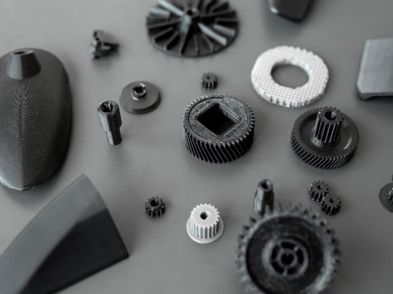



Welcome back to Inslogic Lab Notes. If you print miniatures or decorative statues, dimensional accuracy might not be your top priority. But if you are printing functional parts—like bolts, snap-fit joints, or multi-part enclosures—a fraction of a millimeter can be the difference between a perfect fit and a useless piece of plastic.
There is nothing more frustrating than waiting hours for an assembly to finish, only to realize the peg won't fit into the hole, or the threaded bolt requires a wrench and excessive force just to turn.
If you find yourself constantly reaching for sandpaper, files, or a drill to make your 3D printed parts fit together, you are working too hard. The solution is already in your slicer.
Why Your Printed Parts Don't Fit
Poor dimensional accuracy usually stems from two main factors in FDM printing:
- Material Shrinkage & Expansion: As hot plastic is extruded and cools down, it naturally shrinks. Depending on the material, the cooling process can slightly alter the final dimensions of your holes and outer walls.
- Extrusion Width Expansion: When the nozzle lays down a line of plastic, it often squishes slightly wider than the nozzle diameter. In circular paths (like holes or pegs), this squish tends to push inward, making holes slightly smaller than designed, and pegs slightly thicker.
Many makers try to solve this by going back into their CAD software and manually adding clearance or tolerance to their 3D models. While that works, it is time-consuming and requires you to maintain multiple versions of the same file. Instead, you can let your slicer do the math for you.
The Fix: X-Y Hole & Contour Compensation
Modern slicers (like Bambu Studio, OrcaSlicer, or PrusaSlicer) have a built-in feature specifically designed to correct these microscopic fitting issues. It is called X-Y Hole Compensation (and its partner, X-Y Outer Contour Compensation).
We’ve put together a quick video guide to show you exactly where to find these settings and how to tweak them so your printed assemblies slot together seamlessly on the first try.
Watch: A simple slicer setting trick to help you assemble with ease.
How the Settings Work:
- X-Y Hole (Inner Contour) Compensation: This setting exclusively adjusts hollow profiles (like screw holes or sockets). Increasing this value (e.g., setting it to 0.1mm) will slightly enlarge the hole, giving the peg or screw more breathing room without changing the overall size of the part.
- X-Y Outer Contour Compensation: This setting modifies the outer boundary of your model (like the thickness of a peg or the outer shell of a box). Tweaking this will slightly shrink or expand the outer shape while keeping the internal hole sizes completely unchanged.
By making tiny adjustments here (usually between 0.05mm and 0.15mm), you can dial in the perfect friction fit or free-spinning clearance without ever touching your original CAD file.
The Foundation of Accuracy: Stable Filament
Slicer compensation settings are incredibly powerful, but they rely on one crucial assumption: that your filament is extruding consistently. If your filament diameter fluctuates, or if it is heavily affected by moisture, your line widths will be inconsistent. You cannot accurately compensate for a moving target.
For stable dimensions, reliable snap joints, and mechanical assemblies that require tight tolerances, we highly recommend using engineering-grade filaments.
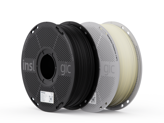
Materials like Inslogic PETG-CF (Carbon Fiber) or Inslogic PC (Polycarbonate) are formulated for extreme dimensional stability. The added carbon fibers in PETG-CF, for example, significantly reduce thermal shrinkage and warping during cooling. This results in consistent dimensional accuracy, incredibly smooth surfaces with barely visible layer lines, and mechanical parts that fit together exactly as intended.
Stop forcing your parts together. Dial in your slicer, load up a high-quality engineering filament, and start printing assemblies that just work.